


All Products
-
 Tayfun from TurkeyVeikong solar pump inverter is really in very good quality and we also prepared some promotional products for exhibition. We are going to make new orders soon. Last year there was only one local agent and this year, there are more than 8. Some of them only sell Veikong!
 -
Cristian from ChileIt’s very good! LCD options make it much easier to use. That’s the strong point, easy of use. And robust. Great PC software.
-
Brahim assad from SyriaVEIKONG VFD500 output frequency is stable when the others are fluctuating. Also output current is less than others, that’s why output frequency is higher too which can save more energy.
Contact Person :
Terry
Phone Number :
008613923736332
WhatsAPP :
+8613923736332
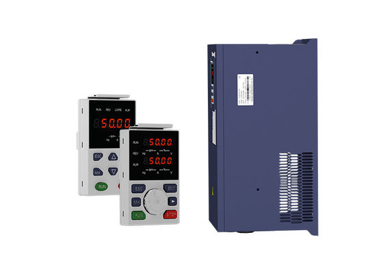
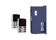
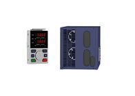
55kw 75hp 220v 380v VFD Variable Frequency Drive Optimal V/F Mode


| Place of Origin | CHINA |
|---|---|
| Brand Name | VEIKONG |
| Certification | CE, ROHS |
| Model Number | VFD500-055G/075GT4B |
| Minimum Order Quantity | 1 |
| Price | Please contact quotation |
| Packaging Details | <45kw inverter be used carton package, ≥45kw be used wood case package |
| Delivery Time | depends on quantities |
| Payment Terms | T/T, Western Union, L/C |
| Supply Ability | 1000 units per week |
Product Details
| Voltage | 380v/220v | Power | 55Kw/75hp |
|---|---|---|---|
| Control Mode | V/f Control, Vector Control | Keypad | LED Keypad, LCD Keypad, Dual Display Keypad |
| Warranty | 18 Months | Protection | Overload,Overvoltage,IP20,Short Circuit,over Heat |
| Highlight | 380v VFD Variable Frequency Drive,75hp VFD Variable Frequency Drive,75hp adjustable frequency drive |
||
Product Description
55kw 75hp 220v 380v vector control inverters frequency drive ac drive
Performance Advantage
Advanced motor control algorithm
High performance open loop vector control
Optimal V/F mode
Excellent ramp slope control
Fast auto-tune (less than 1 minute)
Overload: 150% rated output current, 1 minute
Low frequency torque: 0.5Hz: 100% rated torque 1Hz: 150% rated torque
| Item | Specifiation | |
| Input | Inuput Voltage |
1phase/3phase 220V:200V~240V 3 phase 380V-480V:380V~480V |
| Allowed Voltage fluctuation range | -15%~10% | |
| Input frequency | 50Hz / 60Hz,fluctuation less than 5% | |
| Output | Output Voltage | 3phase:0~input voltage |
| Overload capacity |
General purpose application:60S for 150% of the rated current Light load application:60S for 120% of the rated current |
|
| Control | Control mode |
V/f control Sensorless flux vector control without PG card(SVC) Sensor speed flux vector control with PG card (VC) |
| Operating mode | Speed control,Torque control(SVC and VC) | |
| Speed range |
1:100 (V/f) 1:200( SVC) 1:1000 (VC) |
|
| Speed control accuracy |
±0.5% (V/f) ±0.2% (SVC) ±0.02% (VC) |
|
| Speed response |
5Hz(V/f) 20Hz(SVC) 50Hz(VC) |
|
| frequency range |
0.00~600.00Hz(V/f) 0.00~200.00Hz(SVC) 0.00~400.00Hz(VC) |
|
| Input frequency resolution |
Digital setting: 0.01 Hz Analog setting: maximum frequency x 0.1% |
|
| Startup torque |
150%/0.5Hz(V/f) 180%/0.25Hz(SVC) 200%/0Hz(VC) |
|
| Torque control accuracy |
SVC:within 5Hz10%,above 5Hz5% VC:3.0% |
|
| V/f curve |
V / f curve type: straight line, multipoint, power function, V / f separation; Torque boost support: Automatic torque boost (factory setting), manual torque boost |
|
| Frequency giving ramp |
Support linear and S curve acceleration and deceleration; 4 groups of acceleration and deceleration time, setting range 0.00s ~ 60000s |
|
| DC bus voltage control |
Overvoltage stall control: limit the power generation of the motor by adjusting the output frequency to avoid skipping the voltage fault;
Undervoltage stall control: control the power consumption of the motor by adjusting the output frequency to avoid yaw failure
VdcMax Control: Limit the amount of power generated by the motor by adjusting the output frequency to avoid over-voltage trip; VdcMin control: Control the power consumption of the motor by adjusting the output frequency, to avoid jump undervoltage fault |
|
| Carrier frequency | 1kHz~12kHz(Varies depending on the type) | |
| Startup method |
Direct start (can be superimposed DC brake); speed tracking start |
|
Replace famous brands vfd in general application.
![]()
Failure and diagnosis
The VFD500 inverter has perfect protection. If a fault occurs, the inverter will act according to the fault attribute. For more serious faults, the inverter will directly block the output; for general faults, it can be configured to stop or continue to operate according to the scheduled stop mode. After the inverter fails, the fault relay contacts act and the fault code is displayed on the display panel. Before seeking service, users can perform self-checking according to the tips in this section, analyze the cause of the fault, and find a solution.
| Fault Name | Fault code | Display | Possible Causes | Solutions |
|
Inverter unit protection |
1 | Er. SC |
1: motor insulation aging 2: the cable is damaged and contact, short circuit 3:The distance between motor and inverter are too long. 4: output transistor breakdown 5: the internal wiring of the inverter is loose, or the hardware is bad. 6:brake transistor short circuit |
1. Confirm the insulation resistance of the motor. If it is turned on, replace the motor. 2. Check the power cable of the motor 3. Install reactor or output filter 4, seeking technical support 5, seeking technical support 6. Check if the braking resistor is damaged and the wiring is correct. |
|
Over current during acceleration |
2 | Er.OC1 |
1: The output circuit is grounded or short circuited. 2: Motor auto-tuning is not performed. 3: The acceleration time is too short. 4: Manual torque boost or V/F curve is not appropriate. 5: The voltage is too low. 6: The startup operation is performed on the rotating motor. 7: A sudden load is added during acceleration. 8: The frequency inverter model is of too small power class. |
1: Eliminate external faults. 2: Perform the motor auto- Tuning in cold state 3: Increase the acceleration time. 4: Adjust the manual torque boost or V/F curve. 5: Adjust the voltage to normal range. 6: Select rotational speed tracking restart or start the motor after it stops. 7: Remove the added load. 8: Select a frequency inverter Of higher power class. |
|
Over current during deceleration |
3 | Er.OC2 |
1: The output circuit is grounded or short circuited. 2: Motor auto-tuning is not performed. 3: The deceleration time is too short. 4: The voltage is too low. 5: A sudden load is added during deceleration. 6: The braking unit and braking resistor are not installed |
1: Eliminate external faults. 2: Perform the motor auto-tuning. 3: Increase the deceleration time. 4: Adjust the voltage to normal range. 5: Remove the added load. 6: Install the braking unit And braking resistor. |
|
Over current at constant speed |
4 | Er.OC3 |
1: The output circuit is grounded or short circuited. 2: Motor auto-tuning is notperformed. 3: The voltage is too low. 4: A sudden load is added during operation. 5: The frequency inverter model is of too small power class. |
1:Eliminate external faults. 2: Perform the motor auto-tuning. 3:Adjust The voltage to normal range. 4: Remove the addedload. 5: Select a frequency Inverter of higher power class. |
|
Overvoltage during acceleration |
5 | Er.OU1 |
1:the input voltage is too high 2:The surge voltage is mixed in the input power supply. 3: there is an external force to drive the motor to run, or the brake type load is too heavy 4:the acceleration time is too short 5:the motor is shorted to ground |
1:the power supply voltage is reduced to the normal range 2:install DC reactor 3:Cancel the external force of the draggable motor or install the brake unit 4: increase the acceleration time 5:eliminate the part of the ground short circuit
|
|
Overvoltage during deceleration |
6 | Er.OU2 |
1:the input voltage is too high 2:The surge voltage is mixed in the input power supply. 3: there is an external force to drive the motor to run, or the brake type load is too heavy 4:the decceleration time is too short 5:the motor is shorted to ground |
1:the power supply voltage is reduced to the normal range 2:install DC reactor 3:Cancel the external force of the draggable motor or install the brake unit 4: increase the decceleration time 5:eliminate the part of the ground |
|
Overvoltage at constant speed |
7 | Er.OU3 |
1:the input voltage is too high 2:The surge voltage is mixed in the input power supply. 3: there is an external force to drive the motor to run, or the brake type load is too heavy 4:the acceleration or decceleration time is too short 5:the motor is shorted to ground |
1:the power supply voltage is reduced to the normal range 2:install DC reactor 3:Cancel the external force of the draggable motor or install the brake unit 4: increase the acceleration or decceleration time 5:eliminate the part of the ground |
| Low voltage | 8 | Er.Lv1 |
1: Instantaneous power failure occurs on the input power supply or input phase loss 2: The frequency inverter's input voltage is not within the allowable range. 3: cut off the power during operation 4:the internal wiring of the inverter is loose, or the hardware is bad. |
1:Check if the input power supply is abnormal, whether the input power terminal is loose, whether the input contactor or the air switch is abnormal. 2:adjust the voltage to the normal range 3:Power off after the inverter stops 4:seeking technical support 5: For the unstable power supply, if the performance requirements are low, try to enable the undervoltage stall function (P23.00). |
| Contactor open | 9 | Er.Lv2 |
1: Instantaneous power failure occurs on the input power supply 2: The frequency inverter's input voltage is not within the allowable range. 3: cut off the power during operation 4:the internal wiring of the inverter is loose, or the hardware is bad. |
1:Check if the input power supply is abnormal, whether the input power terminal is loose, whether the input contactor or the air switch is abnormal. 2:adjust the voltage to the normal range 3:Power off after the inverter stops 4:seeking technical support 5: For the unstable power supply, if the performance requirements are low, try to enable the undervoltage stall function (P23.00). |
|
Frequency inverter overload |
10 | Er. oL |
1:The load is too large or the motor is blocked. 2:the large inertia load acceleration and deceleration time is too short 3: When the VF is controlled, the torque boost or V/F curve is not suitable. 4:the frequency converter selection is too small 5:overload at low speed operation |
1. Reduce the load and check the motor and mechanical conditions. 2, increase the acceleration and deceleration time 3. Adjust the torque boost or V/F curve 4, select the inverter with a larger power level 5. Perform motor self-learning in cold state and reduce carrier frequency at low speed |
|
Motor overload |
11 | Er.oL1 |
1:The load is too large or the motor is blocked. 2:the large inertia load acceleration and deceleration time is too short 3:When the VF is controlled, the torque boost or V/F curve is not suitable. 4:the motor selection is too small 5:overload at low speed operation 6:Improper setting of motor parameters and motor protection parameters |
1. Reduce the load and check the motor and mechanical conditions. Correctly set the motor parameters and motor protection parameters. 2, increase the acceleration and deceleration time 3. Adjust the torque boost or V/F curve 4, select a motor with a higher power level 5. Perform motor self-learning in cold state and reduce carrier frequency at low speed 6, check the settings of related parameters |
Recommended Products