-
 Tayfun from TurkeyVeikong solar pump inverter is really in very good quality and we also prepared some promotional products for exhibition. We are going to make new orders soon. Last year there was only one local agent and this year, there are more than 8. Some of them only sell Veikong!
 -
 Cristian from ChileIt’s very good! LCD options make it much easier to use. That’s the strong point, easy of use. And robust. Great PC software.
 -
 Brahim assad from SyriaVEIKONG VFD500 output frequency is stable when the others are fluctuating. Also output current is less than others, that’s why output frequency is higher too which can save more energy.
| Place of Origin | CHINA |
|---|---|
| Brand Name | VEIKONG |
| Certification | CE, ROHS |
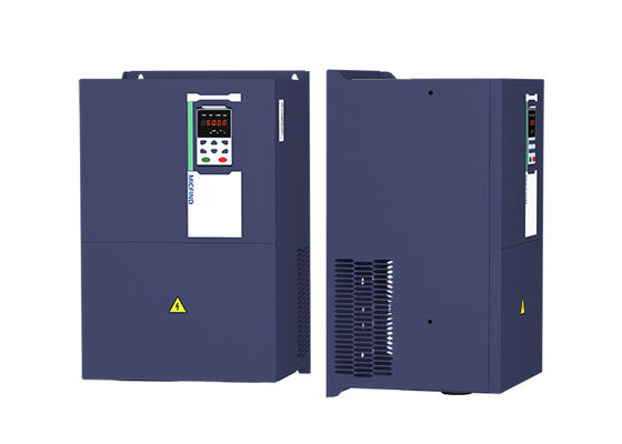
| Model Number | VFD500-045G/055GT4B |
| Minimum Order Quantity | 1 |
| Price | Please contact quotation |
| Packaging Details | <45kw inverter be used carton package, ≥45kw be used wood case package |
| Delivery Time | depends on quantities |
| Payment Terms | T/T, Western Union, L/C |
| Supply Ability | 1000 units per week |
| Name | 40kw 60hp Vfd | Power | 45Kw/60hp |
|---|---|---|---|
| Current | 90A | Control Mode | V/f Control, Vector Control |
| Type | AC Frequency Inverter | Output Voltage | 0-380V |
| Highlight | 60hp Vfd Fan Controller,45kw Vfd Fan Controller,45kw Air Compressor VFD |
||
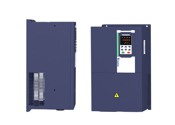
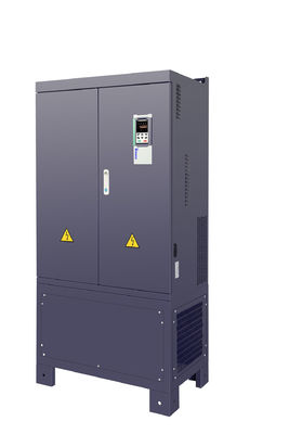
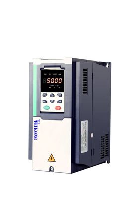
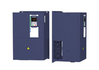
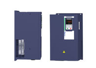
45kw 60hp ac drive inverter vfd for pump fan air compressor vfd
| Item | Specifiation | |
| Input | Inuput Voltage |
1phase/3phase 220V:200V~240V 3 phase 380V-480V:380V~480V |
| Allowed Voltage fluctuation range | -15%~10% | |
| Input frequency | 50Hz / 60Hz,fluctuation less than 5% | |
| Output | Output Voltage | 3phase:0~input voltage |
| Overload capacity |
General purpose application:60S for 150% of the rated current Light load application:60S for 120% of the rated current |
|
| Control | Control mode |
V/f control Sensorless flux vector control without PG card(SVC) Sensor speed flux vector control with PG card (VC) |
| Operating mode | Speed control,Torque control(SVC and VC) | |
| Speed range |
1:100 (V/f) 1:200( SVC) 1:1000 (VC) |
|
| Speed control accuracy |
±0.5% (V/f) ±0.2% (SVC) ±0.02% (VC) |
|
| Speed response |
5Hz(V/f) 20Hz(SVC) 50Hz(VC) |
|
| frequency range |
0.00~600.00Hz(V/f) 0.00~200.00Hz(SVC) 0.00~400.00Hz(VC) |
|
| Input frequency resolution |
Digital setting: 0.01 Hz Analog setting: maximum frequency x 0.1% |
|
| Startup torque |
150%/0.5Hz(V/f) 180%/0.25Hz(SVC) 200%/0Hz(VC) |
|
| Torque control accuracy |
SVC:within 5Hz10%,above 5Hz5% VC:3.0% |
|
| V/f curve |
V / f curve type: straight line, multipoint, power function, V / f separation; Torque boost support: Automatic torque boost (factory setting), manual torque boost |
|
| Frequency giving ramp |
Support linear and S curve acceleration and deceleration; 4 groups of acceleration and deceleration time, setting range 0.00s ~ 60000s |
|
| DC bus voltage control |
Overvoltage stall control: limit the power generation of the motor by adjusting the output frequency to avoid skipping the voltage fault;
Undervoltage stall control: control the power consumption of the motor by adjusting the output frequency to avoid yaw failure
VdcMax Control: Limit the amount of power generated by the motor by adjusting the output frequency to avoid over-voltage trip; VdcMin control: Control the power consumption of the motor by adjusting the output frequency, to avoid jump undervoltage fault |
|
| Carrier frequency | 1kHz~12kHz(Varies depending on the type) | |
| Startup method |
Direct start (can be superimposed DC brake); speed tracking start |
|
VEIKONG inverter work together with famous brands
![]()
Modbus and Canopen communication parameter
| 30 Group Modbus communication parameter | ||||
| P30.00 | Communication type |
0:Modbus; 1:Canopen |
0 | ★ |
| P30.01 | Drive Address |
1~247 Different slaves on the same network should set different local addresses; 0 is the broadcast address, all slave inverters can be identified |
1 | ★ |
| P30.02 | Modbus baud rate |
0:1200 bps; 1:2400 bps 2:4800 bps; 3:9600 bps 4:19200 bps; 5:38400 bps 6:57600 bps; 7:115200 bps |
3 | ★ |
| P30.03 | Modbus data format |
0: 1-8-N-1 (1 start bit +8 data bits +1 stop bits ) 1: 1-8-E-1 (1start bit +8 data bits +1 even parity +1 stop bit) 2: 1-8-0-1 (1 star bit+8 data bits +1odd parity+1 stop bits) 3: 1-8-N-2 (1 star bit+8 data bits+2 stop bits) 4: 1-8-E-2 (1 star bits+8 data bit+1 even parity+2 stop bits) 5: 1-8-0-2 (1 start bit +8 data bits+1 odd parity+2 stop bits) |
0 | ★ |
| P30.04 | Modbus response delay | 1~20msThe delay time of the local to answer the master | 2ms | ★ |
| P30.05 | Modbus overtime | 0.0s(disabled)~60.0s(works for master-slave system) When this function code effective,if slave do not receive data from master overtime,it will trip as Er.485 | 0.0s | ★ |
| r30.06 | Number of frames received by Modbus | Each time a frame is received, this value is incremented by 1,0 to 65535 cycles. | - | ● |
| r30.07 | Number of frames that Modbus has sent | Each time a frame is sent, this value is incremented by 1,0 to 65,536 cycles. | - | ● |
| r30.08 | Number of error frames received by Modbus | Each time an CRC error frame is received, this value is incremented by 1,0 to 65535 cycles; it can be used to judge the degree of communication interference. | - | ● |
| P30.09 | Modbus master-slave option | 0: Slave 1: Master(sent by broadcast ) |
0 | ★ |
| P30.10 | Slave memory when inverter as master | 1~9 corresponds to 0x7001~0x7009 | 1 | ☆ |
| P30.11 | Data sent by Master |
0:output frequency 1:set frequency 2:output torque 3:set torque 4:PID setting 5:PID feedback 6:output current |
0 | ☆ |
| P30.12 | Sending interval of Master | 0.010~10.000sAs a master, after sending one frame of data, the next frame of data is sent after this delay. | 0.1s | ☆ |
| P30.13 | Receiving proportaionality factor of slave | -10.000~10.000The values of slave registers 0x7001 and 0x7002 take effect after passing through this scaling factor | 1.00 | ☆ |
| P30.14 | Communication special register speed unit |
0: 0.01% 1: 0.01Hz 2: 1Rpm Some units of specific communication registers can be set by this parameter. See Appendix A for details. |
0 | ☆ |
| P30.15 | Modbus response characteristics |
When the format of the received frame is a write register, this parameter can be set to reply to the host. 0: Reply to the host (standard Modbus protocol) 1: Do not reply to the host (non-standard Modbus protocol) |
0 | ☆ |
| 31 Group Canopen communication parameter | ||||
| P31.00 | CANopen communication address | 1 ~ 127 | 1 | ☆ |
| P31.01 | CANopen Baud rate |
0:100k 1:125k 2:250k 3:500k 4:1M |
3 | ☆ |
| P31.02 | CANopen overtime | 1ms ~ 20ms | 4ms | ☆ |
| r31.07 | CANopen version number | Display the version number of the CANopen card | - | ● |
| r31.08 | CANopen Working status |
0: Initialisation status 1: Disconnected 2: Connecting/Preparing- 3: Stopped 4: Operational status 5: Pre_operational |
- | ● |
| r31.10 | CANopen receive error count | The number of error frames received by CANopen is not saved after power off | - | ● |
| r31.11 | CANopen send error count | The number of frames sent by CANopen is not saved after power off | - | ● |
| r31.12 | CANopen receive frame number | The number of frames received by CANopen is not saved after power off | - | ● |
| r31.14 | CANopen send frame number | The number of frames sent by CANopen is not saved after power off | - | ● |


