


All Products
-
 Tayfun from TurkeyVeikong solar pump inverter is really in very good quality and we also prepared some promotional products for exhibition. We are going to make new orders soon. Last year there was only one local agent and this year, there are more than 8. Some of them only sell Veikong!
 -
Cristian from ChileIt’s very good! LCD options make it much easier to use. That’s the strong point, easy of use. And robust. Great PC software.
-
Brahim assad from SyriaVEIKONG VFD500 output frequency is stable when the others are fluctuating. Also output current is less than others, that’s why output frequency is higher too which can save more energy.
Contact Person :
Terry
Phone Number :
008613923736332
WhatsAPP :
+8613923736332
15KW 18.5KW Variable Frequency Inverters


Product Details
| Product Name | 380V 11KW 15KW 18.5KW Variable Frequency Inverters | Application | Motor, Fan, Pump, Mixer |
|---|---|---|---|
| Display | LED/LCD | Warranty | 18 Months |
| Current | 25A、32A、37A | Frequency | 50HZ/60HZ |
| Highlight | 18.5KW Variable Frequency Inverters,15KW Variable Frequency Inverters |
||
Product Description
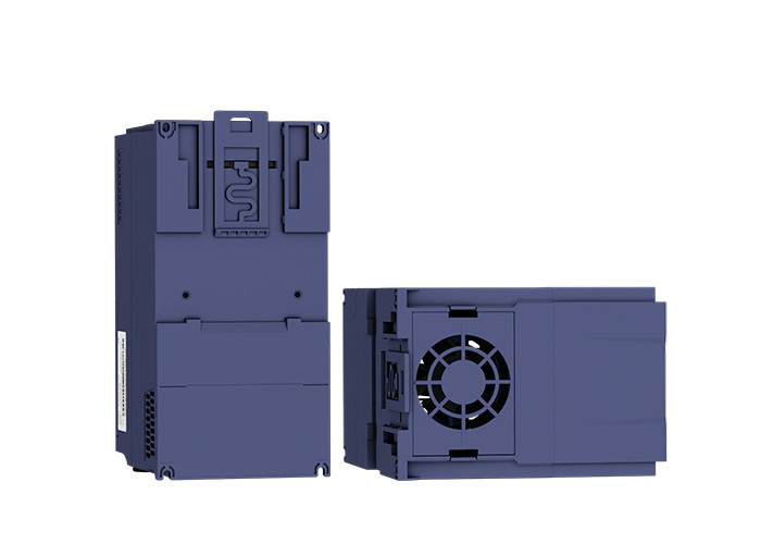
380V 11KW 15KW 18.5KW Variable Frequency Inverters For AC Motor
1. Deceleration over excitation function
Accurate thermal simulation platform software ensures the reliability of thermal simulation.
Each VFD500 inverter has undergone thermal simulation testing, and only the physical prototype is developed within the scope of the thermal simulation safety design requirements. After the actual test, the thermal simulation results are very close to the physical test results. In the limit test state, the thermal simulation can replace the actual load simulation and an additional layer of scientific thermal test.
2. Powerful Torque Characteristics
Powerful torque at 0 Hz, without sensors or feedback devices. Until recently, sensorless control has been out of reach for synchronous motors.
VFD500 series provides powerful starting torque algorithm without relying on pole sensors or motor feedback.
High-performance current vector control achieves powerful starting torque with an induction motor.
![]()
Techinical Specifications
|
Item |
Specifiation |
|
|
Input |
Input Voltage |
1phase/3phase 220V:200V~240V 3 phase 380V-480V:380V~480V |
|
Allowed Voltage fluctuation range |
-15%~10% |
|
|
Input frequency |
50Hz / 60Hz,fluctuation less than 5% |
|
|
Output |
Output Voltage |
3phase:0~input voltage |
|
Overload capacity |
General purpose application:60S for 150% of the rated current Light load application:60S for 120% of the rated current |
|
|
Control |
Control mode |
V/f control Sensorless flux vector control without PG card(SVC) Sensor speed flux vector control with PG card (VC) |
|
Operating mode |
Speed control,Torque control(SVC and VC) |
|
|
Speed range |
1:100 (V/f) 1:200( SVC) 1:1000 (VC) |
|
|
Speed control accuracy |
±0.5% (V/f) ±0.2% (SVC) ±0.02% (VC) |
|
|
Speed response |
5Hz(V/f) 20Hz(SVC) 50Hz(VC) |
|
|
frequency range |
0.00~600.00Hz(V/f) 0.00~200.00Hz(SVC) 0.00~400.00Hz(VC) |
|
|
Input frequency resolution |
Digital setting: 0.01 Hz Analog setting: maximum frequency x 0.1% |
|
|
Startup torque |
150%/0.5Hz(V/f) 180%/0.25Hz(SVC) 200%/0Hz(VC) |
|
|
Torque control accuracy |
SVC:within 5Hz10%,above 5Hz5% VC:3.0% |
|
|
V/f curve |
V / f curve type: straight line, multipoint, power function, V / f separation; Torque boost support: Automatic torque boost (factory setting), manual torque boost |
|
|
Frequency giving ramp |
Support linear and S curve acceleration and deceleration; 4 groups of acceleration and deceleration time, setting range 0.00s ~ 60000s |
|
|
DC bus voltage control |
Overvoltage stall control: limit the power generation of the motor by adjusting the output frequency to avoid skipping the voltage fault;
Undervoltage stall control: control the power consumption of the motor by adjusting the output frequency to avoid yaw failure
VdcMax Control: Limit the amount of power generated by the motor by adjusting the output frequency to avoid over-voltage trip; VdcMin control: Control the power consumption of the motor by adjusting the output frequency, to avoid jump undervoltage fault |
|
|
Carrier frequency |
1kHz~12kHz(Varies depending on the type) |
|
|
Startup method |
Direct start (can be superimposed DC brake); speed tracking start |
|
|
Stop method |
Deceleration stop (can be superimposed DC braking); free to stop |
|
|
Maincontrol function |
Jog control, droop control, up to 16-speed operation, dangerous speed avoidance, swing frequency operation, acceleration and deceleration time switching, VF separation, over excitation braking, process PID control, sleep and wake-up function, built-in simple PLC logic, virtual Input and output terminals, built-in delay unit, built-in comparison unit and logic unit, parameter backup and recovery, perfect fault record,fault reset, two groups of motor parametersfreeswitching, software swap output wiring, terminals UP / DOWN |
|
|
Function |
Keypad |
LED Digital keyboard and LCD keypad(option) |
|
Communication |
Standard: MODBUS communication CAN OPEN AND PROFINET( IN DEVELOPMENT) |
|
|
PG card |
Incremental Encoder Interface Card (Differential Output and Open Collector), Rotary transformer Card |
|
|
Input terminal |
Standard: 5 digital input terminals, one of which supports high-speed pulse input up to 50kHz; 2 analog input terminals, support 0 ~ 10V voltage input or 0 ~ 20mA current input; Option card: 4 digital input terminals 2 analog input terminals.support-10V-+10V voltage input |
|
|
Output terminal |
standard: 1 digital output terminal; 1 high-speed pulse output terminal (open collector type), support 0 ~ 50kHz square wave signal output; 1 relay output terminal(second relay is an option ) 2 analog output terminals, support 0 ~ 20mA current output or 0 ~ 10V voltage output; Option card: 4 digital output terminals |
|
|
Protection |
Refer to Chapter 6 "Troubleshooting and Countermeasures" for the protection function |
|
|
Environment |
Installation location |
Indoor, no direct sunlight, dust, corrosive gas, combustible gas, oil smoke, vapor, drip or salt. |
|
Altitude |
0-3000m.inverter will be derated if altitude higher than1000m and rated output current will reduce by 1% if altitude increase by 100m |
|
|
Ambient temperature |
-10°C~ +40°C,maximum 50°C (derated if the ambient temperature is between 40°C and 50°C)Rated output current decrease by 1.5% if temperature increase by 1°C |
|
|
Humidity |
Less than 95%RH, without condensing |
|
|
Vibration |
Less than 5.9 m/s2 (0.6 g) |
|
|
Storage temperature |
-20°C ~ +60°C |
|
|
Others |
Installation |
Wall-mounted, floor-controlled cabinet, transmural |
|
Protection level |
IP20 |
|
|
cooling method |
Forced air cooling |
|
|
EMC |
CE ROHS |
Internal EMC filter Complies with EN61800-3 Category C3 3rd Environment |
Standard wiring diagram
![]()
Product Application
![]()
![]()
FAQ:
1. What voltage range can you support?
Single-phase 220v input, single-phase 220v output;
Single-phase 220v input, three-phase 220v output;
Three-phase 220v input, three-phase 220v output;
Single-phase 220v input, three-phase 380v output;
380v input, 380v output, from 0.4KW-710KW.
2. What is the standard of package?
Below 37kw, it's carton package; 45kw and above, it's wooden package.
3. Do you accept OEM business?
We accept OEM and ODM with your autherization.
Recommended Products