


All Products
-
 Tayfun from TurkeyVeikong solar pump inverter is really in very good quality and we also prepared some promotional products for exhibition. We are going to make new orders soon. Last year there was only one local agent and this year, there are more than 8. Some of them only sell Veikong!
 -
Cristian from ChileIt’s very good! LCD options make it much easier to use. That’s the strong point, easy of use. And robust. Great PC software.
-
Brahim assad from SyriaVEIKONG VFD500 output frequency is stable when the others are fluctuating. Also output current is less than others, that’s why output frequency is higher too which can save more energy.
Contact Person :
Terry
Phone Number :
008613923736332
WhatsAPP :
+8613923736332
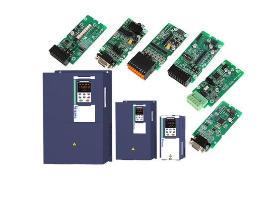
Vector Control 220v 10 Hp Vfd Single Phase Input To Three Phase Converter


| Place of Origin | CHINA |
|---|---|
| Brand Name | VEIKONG |
| Certification | CE, ROHS |
| Model Number | VFD500-011G/015GT4B |
| Minimum Order Quantity | 1 |
| Price | Please contact quotation |
| Packaging Details | <45kw inverter be used carton package, ≥45kw be used wood case package |
| Delivery Time | depends on quantities |
| Payment Terms | T/T, Western Union, L/C |
| Supply Ability | 1000 units per week |
Product Details
| Name | 10hp Vfd | Power | 7.5kw/10hp |
|---|---|---|---|
| Control Mode | V/f Control, Vector Control | Output Frequency | 50Hz/60Hz |
| Protection | Overload,Overvoltage,IP20,Short Circuit,over Heat | Application | Pump,Motor And Pump,Compressor Etc |
| Highlight | Vector control 10 Hp Vfd,220v 10 Hp Vfd,10Hp vector control vfd |
||
Product Description
10HP vfd ac 220v single phase input 3 phase output frequency inverter
VEIKONG VFD500 features and technicail data
1, With inside EMC C3 filter and building-block design for IO extension card and different kinds of PG card
2, Top performance in our industry which represent in torque in less than 1hz 0.5hz 0.25hz 0.1hz and 0hz
it can compare with any domestic chinese brand for output torque.
3, Smooth running and stability, support optional LCD keypad and dual display keypad. support PC tools.
4, Support modbus485, canopen, profinet communciation.
5, Low noise on motor and fast response for 0.1S acceleration and deceleration without dead zone
6, Reverse and forward free switching
7, Sleeping function and energy saving function as well as in built PLC programming
8, Tension control and torque mode control
9, Support two group motor parameters which can realize two motor switching control
| Item | Specifiation | |
| Input | Inuput Voltage |
1phase/3phase 220V:200V~240V 3 phase 380V-480V:380V~480V |
| Allowed Voltage fluctuation range | -15%~10% | |
| Input frequency | 50Hz / 60Hz,fluctuation less than 5% | |
| Output | Output Voltage | 3phase:0~input voltage |
| Overload capacity |
General purpose application:60S for 150% of the rated current Light load application:60S for 120% of the rated current |
|
| Control | Control mode |
V/f control Sensorless flux vector control without PG card(SVC) Sensor speed flux vector control with PG card (VC) |
| Operating mode | Speed control,Torque control(SVC and VC) | |
| Speed range |
1:100 (V/f) 1:200( SVC) 1:1000 (VC) |
|
| Speed control accuracy |
±0.5% (V/f) ±0.2% (SVC) ±0.02% (VC) |
|
| Speed response |
5Hz(V/f) 20Hz(SVC) 50Hz(VC) |
|
| frequency range |
0.00~600.00Hz(V/f) 0.00~200.00Hz(SVC) 0.00~400.00Hz(VC) |
|
| Input frequency resolution |
Digital setting: 0.01 Hz Analog setting: maximum frequency x 0.1% |
|
| Startup torque |
150%/0.5Hz(V/f) 180%/0.25Hz(SVC) 200%/0Hz(VC) |
|
| Torque control accuracy |
SVC:within 5Hz10%,above 5Hz5% VC:3.0% |
|
| V/f curve |
V / f curve type: straight line, multipoint, power function, V / f separation; Torque boost support: Automatic torque boost (factory setting), manual torque boost |
|
| Frequency giving ramp |
Support linear and S curve acceleration and deceleration; 4 groups of acceleration and deceleration time, setting range 0.00s ~ 60000s |
|
| DC bus voltage control |
Overvoltage stall control: limit the power generation of the motor by adjusting the output frequency to avoid skipping the voltage fault;
Undervoltage stall control: control the power consumption of the motor by adjusting the output frequency to avoid yaw failure
VdcMax Control: Limit the amount of power generated by the motor by adjusting the output frequency to avoid over-voltage trip; VdcMin control: Control the power consumption of the motor by adjusting the output frequency, to avoid jump undervoltage fault |
|
| Carrier frequency | 1kHz~12kHz(Varies depending on the type) | |
| Startup method |
Direct start (can be superimposed DC brake); speed tracking start |
|
| Stop method | Deceleration stop (can be superimposed DC braking); free to stop | |
| Maincontrol function | Jog control, droop control, up to 16-speed operation, dangerous speed avoidance, swing frequency operation, acceleration and deceleration time switching, VF separation, over excitation braking, process PID control, sleep and wake-up function, built-in simple PLC logic, virtual Input and output terminals, built-in delay unit, built-in comparison unit and logic unit, parameter backup and recovery, perfect fault record,fault reset, two groups of motor parametersfreeswitching, software swap output wiring, terminals UP / DOWN | |
| Function | Keypad | LED Digital keyboard and LCD keypad(option) |
| Communication |
Standard: MODBUS communication CAN OPEN AND PROFINET( IN DEVELOPMENT) |
|
| PG card | Incremental Encoder Interface Card (Differential Output and Open Collector), Rotary transformer Card | |
| Input terminal |
Standard: 5 digital input terminals, one of which supports high-speed pulse input up to 50kHz; 2 analog input terminals, support 0 ~ 10V voltage input or 0 ~ 20mA current input; Option card: 4 digital input terminals 2 analog input terminals.support-10V-+10V voltage input |
|
| Output terminal |
standard: 1 digital output terminal; 1 high-speed pulse output terminal (open collector type), support 0 ~ 50kHz square wave signal output; 1 relay output terminal(second relay is an option ) 2 analog output terminals, support 0 ~ 20mA current output or 0 ~ 10V voltage output; Option card: 4 digital output terminals |
|
| Protection | Refer to Chapter 6 "Troubleshooting and Countermeasures" for the protection function | |
| Environment | Installation location | Indoor, no direct sunlight, dust, corrosive gas, combustible gas, oil smoke, vapor, drip or salt. |
| Altitude | 0-3000m.inverter will be derated if altitude higher than1000m and rated output current will reduce by 1% if altitude increase by 100m | |
| Ambient temperature | -10°C~ +40°C,maximum 50°C (derated if the ambient temperature is between 40°C and 50°C)Rated output current decrease by 1.5% if temperature increase by 1°C | |
| Humidity | Less than 95%RH, without condensing | |
| Vibration | Less than 5.9 m/s2 (0.6 g) | |
| Storage temperature | -20°C ~ +60°C | |
| Others | Installation | Wall-mounted, floor-controlled cabinet, transmural |
| Protection level | IP20 | |
| cooling method | Forced air cooling | |
| EMC | CE ROHS |
Internal EMC filter Complies with EN61800-3 Category C3 3rd Environment |
VEIKONG big power VFD250KW VFD355KW project
![]()
![]()
![]()
PID function
| 40 Group PID function | ||||
| r40.00 | PID final output value | Read only unit:0.1% | - | ● |
| r40.01 | PID final set value | Read only unit:0.1% | - | ● |
| r40.02 | PID final feedback value | Read only unit:0.1% | - | ● |
| r40.03 | PID deviation value | Read only unit:0.1% | - | ● |
| P40.04 | PID reference source |
Unit’s digit:PID main reference source(ref1) 0:Digtital setting 1:AI1 2:AI2 3:AI3(IO expansion board) 4:AI4(IO expansion board) 5:HDI high frequency pulse 6:Communication Ten’s digit:PID Auxilary reference source(ref2)Same as Unit’s digit |
00 | ☆ | |||||||||||||||
| P40.05 | PID given feedback range | 0.01~655.35 | 100.00 | ☆ | |||||||||||||||
| P40.06 | PID digital setting 0 | 0.0~P40.05 | 0.0% | ☆ | |||||||||||||||
| P40.07 | PID digital setting 1 | 0.0~P40.05 | 0.0% | ☆ | |||||||||||||||
| P40.08 | PID digital setting 2 | 0.0~P40.05 | 0.0% | ☆ | |||||||||||||||
| P40.09 | PID digital setting 3 | 0.0~P40.05 | 0.0% | ☆ | |||||||||||||||
|
When PID reference source is digital setting, PID digital setting 0~3 depends on DI terminal function 43 (preset PID terminal I ) and 44 ( preset PID terminal 2):
For example: When AI1 is used as PID feedback, if the full range corresponds to 16.0kg pressure and require PID control to be 8.0kg; then set P40.05 PID feedback range to 16.00, PID digital reference terminal select to P40.06, Set P40.06 (PID preset setting 0) to be 8.00
|
|||||||||||||||||||
|
When PID reference source is digital setting, PID digital setting 0~3 depends on DI terminal function 43 (preset PID terminal I ) and 44 ( preset PID terminal 2):
For example: When AI1 is used as PID feedback, if the full range corresponds to 16.0kg pressure and require PID control to be 8.0kg; then set P40.05 PID feedback range to 16.00, PID digital reference terminal select to P40.06, Set P40.06 (PID preset setting 0) to be 8.00
|
||||||||||||||||||||
| P40.10 | PID reference source selection | 0:ref1 1:ref1+ref2 2:ref1-ref2 3:ref1*ref2 4:ref1/ref2 5:Min(ref1,ref2) 6:Max(ref1,ref2) 7(ref1+ref2)/2 8: fdb1and fdb2 switchover |
0 | ☆ | ||||||||||||||||
| P40.11 | PID feedback source1 |
Unit’s digit 0:PID feedback source1(fdb1) 0:AI1 1:AI2 2:AI3(option card) 3:AI4(option card) 4: PLUSE(HDI) 5: Communication 6: Motor rated output current 7: Motor rated output frequency 8: Motor rated output torque 9: Motor rated output frequency Ten’s digit : PID feedback source2 (fdb2) Same as Unit’s digit |
00 | ☆ | ||||||||||||||||
| P40.13 | PID feedback function selection | 0:fdb1 1:fdb1+fdb2 2:fdb1-fdb2 3:fdb1*fdb2 4:fdb1/fdb2 5:Min(fdb1,fdb2)Take fdb1.fdb2 smaller value 6:Max(fdb1,fdb2) Take fdb1.fdb2 bigger value 7: (ref1+ref2)/2 8: fdb1and fdb2 switchover |
0 | ☆ | ||||||||||||||||
| P40.14 | PID output feature |
0: PID output is positive: when the feedback signal exceeds the PID reference value, the output frequency of the inverter will decrease to balance the PID. For example, the strain PID control during wrapup 1: PID output is negative: When the feedback signal is stronger than the PID reference value, the output frequency of the inverter will increase to balance the PID. For example, the strain PID control during wrapdown |
0 | ☆ | ||||||||||||||||
|
The PID output characteristic is determined by P40.14 and Di terminal 42 function PID positive/negative switching: P40.14 = 0 and "42: PID positive/negative switching" terminal is invalid: : PID output characteristic is positive P40.14 = 0 and "42: PID positive/negative switching" terminal is valid: : PID output characteristic is negative P40.14 = 1 and "42: PID positive/negative switching" terminal is invalid: : PID output characteristic is negative P40.14 = 1 and "42: PID positive/negative switching" terminal is valid: : PID output characteristic is positive |
||||||||||||||||||||
| P40.15 | Upper limit of PID output | -100.0%~100.0% | 100.0% | ☆ | ||||||||||||||||
| P40.16 | lower limit of PID output | -100.0%~100.0% | 0.0% | ☆ | ||||||||||||||||
| P40.17 | Proportaional gain KP1 |
0.00~10.00 The function is applied to the proportional gain P of PID input. P determines the strength of the whole PID adjuster. The parameter of 100 means that when the offset of PID feedback and given value is 100%, the adjusting range of PID adjust is the Max. frequency (ignoring integral function and differential function).
|
5.0% | ☆ | ||||||||||||||||
| P40.18 | Integral time TI1 |
0.01s~10.00s This parameter determines the speed of PID adjustor to carry out integral adjustment on the deviation of PID feedback and reference. When the deviation of PID feedback and reference is 100%, the integral adjustor works continuously after the time (ignoring the proportional effect and differential effect) to achieve the Max. Frequency (P01.06) or the Max. Voltage (P12.21). Shorter the integral time, stronger is the adjustment
|
1.00s | ☆ | ||||||||||||||||
| P40.19 | Differential time TD1 |
0.000s~10.000s This parameter determines the strength of the change ratio when PID adjustor carries out integral adjustment on the deviation of PID feedback and reference. If the PID feedback changes 100% during the time, the adjustment of integral adjustor (ignoring the proportional effect and differential effect) is the Max. Frequency (P01.06) or the Max. Voltage (P12.21). Longer the integral time, stronger is the adjusting.
|
0.000s | ☆ | ||||||||||||||||
| P40.20 | Proportaional gain KP2 | 0.00~200.0%. | 5.0% | ☆ | ||||||||||||||||
| P40.21 | Integral time TI2 |
0.00s (no any integral effect )~20.00s
|
1.00s | ☆ | ||||||||||||||||
| P40.22 | Differential time TD2 | 0.000s~0.100s | 0.000s | ☆ | ||||||||||||||||
| P40.23 | PID parameter switchover condition |
0:no switchover Do not switch, use KP1, TI1, TD1 Switch by DI terminal KP1, TI1, TD1 are used when DI terminal No. 41 function is invalid; KP2, TI2, TD2 are used when valid The absolute value of PID command and feedback deviation is less than P40.24, using KP1, TI1, TD1; the absolute value of deviation is greater than P40.25, using KP2, TI2, TD2 parameters; the absolute value of deviation is between P40.24~P40.25, The two sets of parameters are linearly transitioned. |
0 | ☆ | ||||||||||||||||
| P40.24 | PID parameter switchover devation 1 | 0.0%~P40-25 | 20.0% | ☆ | ||||||||||||||||
| P40.25 | PID parameter switchover devation 2 | P40-24~100.0% | 80.0% | ☆ | ||||||||||||||||
|
In some applications, one group PID parameter is not enough, different PID parameters would be adopted according to the situation. The function codes are used to switch two groups PID parameter. The setting mode of the regulator parameters P40.20~P40.22 is similar as P40.17~P40.19’s. Two groups PID parameter can be switched via DI terminal, or switched according to PID deviation automatically. When selection is automatic switching: when the deviation absolute value between given and feedback is smaller than P40.24 (PID parameter switching deviation 1), PID parameter selection is group 1. When the deviation absolute value between given and feedback is bigger than P40.25 (PID parameter switching deviation 2), PID parameter selection is group 2. When the deviation absolute value between given and feedback is between P40.24 and P40.25, PID parameter is the linear interpolation of two groups PID parameter, showed as below parameter switching diagram |
||||||||||||||||||||
Recommended Products